Thursday, May 28, 2015

Day 26

  This picture shows the graph and equation of alternating current and voltage.

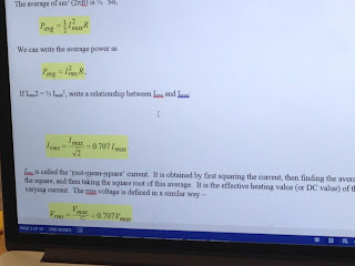
  These pictures show the relationship of Vrms,Vmax,Irms and Imax.


  There is an example problem we did in class.

  We started to do the alternating currents and voltages experiment on the lab manual.

  This is our set up for the lab.

  These two graphs are the alternating current graph and alternating voltage graph we found by using Logger Pro.

  We calculated the Vmax,Vrms and theoretical Vrms, then we calculate the percent error.

  We calculated the Imax,Irms and theoretical Irms, then we calculate the percent error.

  We found out the amptitude of current is longer than voltage.

  This is a example problem that professor gave us, we need to calculate Xc and Irms.

  Then we started capacitors in an AC circuit lab.

  This is our set up for the lab. We set frequency is 100 Hz and voltage is 2 V.

  There are the graphs of current and voltage. And we found Imax is 0.116A and Vmax is 2.005V.

  We found the Vrms, Irms, theoretical capacitive reactance and experimental capacitive reactance. Then we calculate the percent error is 18%.


  We calculate Irms by hand to make sure our data is correct.

  We found a new equation I=-V_max/wL*cos(wt+theta)usingV=V_max*sin(wt+theta).

  There is a example problem professor gave us. We need to calculate XL and Irms.

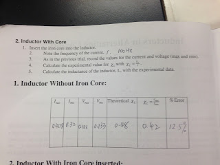
  We started to do inductors in alternating circuits experiment on the lab manual.

  There are current graph and voltage graph we found for the experiment by using Logger Pro.

  This is the chart we filled by using the data we collected.


Conclusion:
  Today, we did many experiments about Vrms,Vmax,Irms and Imax. First, professor showed us the equations and graphs about alternating current and voltage. Then we started to do alternating current and voltage lab to found Vrms,Vmax,Irms and Imax and calculate the percent error. Then we did some exercise to calculated Irms. After, we did inductors in alternating circuit lab and capacitors in AC circuit lab which same as alternating current and voltage lab, find Vrms,Vmax,Irms and Imax, then calculate percent error.

Tuesday, May 26, 2015

Day 25

  By Faraday's law, change in current through the inductor will change the magnetic field, it produces an induced EMF.

  This is a current vs. time graph. As time goes long, inductor voltage will decrease and current will increase.

  Then professor gave us a problem to solve. We known resistor is 100 o, we know the area of the inductor and it is 110 turn. So we could found L.


  Then we calculate the resistant of the wire and found the time constant by using the equation L/R.

  Then we found period is 2.55*10^-5.

  We started doing an oscilloscope experiment.

  These two pictures show our set up. We connect the function generate, oscilloscope, resistor and inductor as a circuit.


  First, we found out the time constant is 4.9*10^-6 by using the equation t_1/2 divide ln2. Then we used equation L/R to found L. Last, we found N is 108 which is very close to 110.


  Then we started to do a question that professor gave us.


  There are the answer we found out.


Conclusion:
  Everything we did today is about inductor. First, we learned Faraday's law. Then used the information that professor gave us to calculate L and time constant. After, we did an experiment to prove our calculation is very close to experimental answers. Last, we did a long problem that professor gave us.

Tuesday, May 19, 2015

Day 24

  At beginning of the class, we did a online exercise about magnetic flux and EMF.


  These are the answer for the online exercise.

  These pictures show the experiment we did in class. When professor gave current to the stick, the stick will move. Then, professor gave opposite direction of current, the stick will move opposite way.


  This is the diagram we draw to explain the experiment.

  This is another online exercise we did in class, it is about motional EMF.


  There are the answers for the exercise.

  We use the equation V=L*dI/dt, V=RI and C=Q/V to find that V=1/C integral I dt.

  Then we found out L= u*N^2*A/L.

  We used the equation we found above to calculate a problem and the answer we got is 9.87*10^-7 H.

  This picture shows the unit we found for L and J.

  There is the diagram we draw for a RC circuit. And a I vs. t graph.

  In this picture, professor showed us the relationship of T, L and R.

  This is the last online exercise we did in class, it is about RC circuit.


Conclusion:
  Today, we did lots of online exercise and an interesting experiment. First, we did a online exercise about magnetic flux and EMF. Then professor showed us a experiment, when gave current to a copper stick, the stick will move; if give opposite direction of current, the stick will also move opposite direction. After, we found out a new equation L= u*N^2*A/L. Last, we did another online exercise about RC circuit.